This blog is a place for me to share with you all of my major projects. For quick updates regarding my work, view my Google+ profile, accessible via the About Me section below.
There is a light switch on the wall at the entrance of the bedroom in my apartment. You would imagine it would turn on the bedroom lights, but since there are not ceiling lights in the bedroom, it can't do that. What it actually controls is the power to a single receptacle on the wall. In the past, I've had two lamps plugged into this one receptacle. The lamps sit on nightstands on either side of the bed, but there is a problem. Imagine you're getting ready for bed. It's dark out, so as you walk into the bedroom, you flip the light switch on and the lamps come on. Just as expected. Now you're going to bed and you want the lights off - you have two choices: go to the wall and flip the switch again, or individually turn the lamp's power switches off. Of course you're not going to get out of a warm and comfortable bed to flip the light switch so you turn the lamps off. Now here's the dilemma. In the morning, you want the lights back on, right? You have to clumsily reach under both lampshades to turn the lights back on because the light switch won't do squat if the lamps are powered off. That's what this project aims to solve. The light switch will work as any other light switch does - flip it up and both lamps come on and down to turn them both off. Each lamp will have a switch that not only has the ability to turn that lamp on or off, but also to control the other lamp just as easily. And finally, have control of the lights and read their status over the internet. Because this is the future and I want to turn lights on I can't even see. Read on to see how to do it.
I knew the end goal of my project, but I went through a ton of ideas before getting there. The most difficult part for me was safely and reliably detecting when the light switch in the bedroom was on without modifying the apartment's wiring. My first idea was to add a simple wall wart that would spit out a DC voltage that I could detect with a microcontroller. This was certainly overkill and in practice, it wasn't fast enough to detect when it is shut off because, without a load, the filtering capacitors would hold a charge for a long time. My next step was to design my own power supply but I soon realized, I couldn't design something smaller than a commercial product. I also experimented with transformer-less power supplies but was not happy with how dangerous they were. So the next plan of action was to create a non-contact AC voltage detector. I tried out a few designs but could not find one that would reliably detect the AC voltage in one receptacle while being powered from the other receptacle, so I scrapped this idea too. Then I finally found the idea that would work! I would use an opto-isolator. Unfortunately, I did not have a suitable one on hand, so instead of ordering one, I would make my own.
Experimenting with ways to detect if AC voltage is present
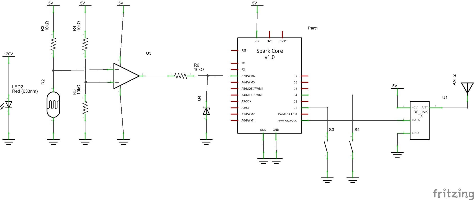
My design uses a 120V ac lamp and a light-dependent resistor plus a op-amp configured as a comparator to detect if the AC power on the receptacle connected to the wall's light switch is on or off. I 3D-printed a case for the lamp and LDR to reside in. I normally post files, but these are as simple as they come and I can't think of a reason anybody would want files that are so specific. The LDR has a resistance of approximately 400kΩ when dark and 400Ω when light. I put this in series with a 10kΩ resistor and a 5V source to form a voltage divider. When dark, the voltage is near the source voltage, and when light, it is near 0V. During my experiments, it is not quite in logic levels, so I used a comparator with a threshold at half of the source voltage to ensure I always get a "1" or "0". Since the op amp that I used required at least a 5V source, and my microcontroller is only 3.3V tolerant, I used a 3.3V zener diode to ensure that 3.3V is on and 0V is off. Now I have a opto-isolator that can detect whether or not a 120V AC receptacle is powered on with a 3.3V output logic level.
I saw other projects across the web using the EtekcityWireless Remote Control Outlets, so I knew they were a great fit for my project too. Plus they are very inexpensive compared to other remote outlets that some Smart Home companies offer. I bought an RFToy from the Rayshobby Store to read the addresses for my outlets, and it is an awesome gadget for doing so. It's essentially a remote that can record the on and off codes for each outlet and then play them back on demand. Of course, this is completely unnecessary, because the rc-switch arduino library has a RecieveDemo sketch that prints out the same data over serial. Both methods require the proper frequency receiver and transmitter (with the appropriate length wire for an antenna) to get the wireless data. The Etekcity outlets operate at 433MHz.
Testing the switches using the RFToy
The next step was writing the firmware for controlling the lamps and outlets. I first had to decide which microcontroller I would use for this project. Over the years, I have amassed quite the collection from samples, giveaways, and Kickstarters so I had many choices. I knew I wanted some kind of smart phone control so I narrowed it down to a BLEduino or a Spark Core. The Spark's documentation is leaps and bounds better than the BLEduino, so I decided to use it for this project. The rc-switch library has already been ported to the Spark, so I was able to quickly make a demo project that showed the wireless outlets worked in conjunction with a button for control. While researching ways to debounce the buttons, I ran across the awesome clickbutton library and it's capabilities allowed me to adjust the firmware's logic for some advanced features. As I mentioned earlier, each lamp has it's own button. Using this library, I gave the buttons three ways of being "clicked". There is the single click which toggles that lamp, the double click which toggles the other lamp, and the long click which toggles that lamp and sets the other lamp to the same state. For instance, if your lamp is on and you long click, your lamp will turn off and so will the other lamp. This is beneficial if you want to change the state of both lamps without thinking about them. While these libraries took care of most of the hard work, I also added an interrupt for the light switch input that will set both lamps to the state of the light switch whenever its state changes. As for the internet connectivity, I also added a Spark function that allows the state of the lamps to be changed over the internet and a function that will return the state of the lamp. Read below for how I implemented it. All of the firmware for this project is hosted on GitHub.
Schematic for this project (click for full size)
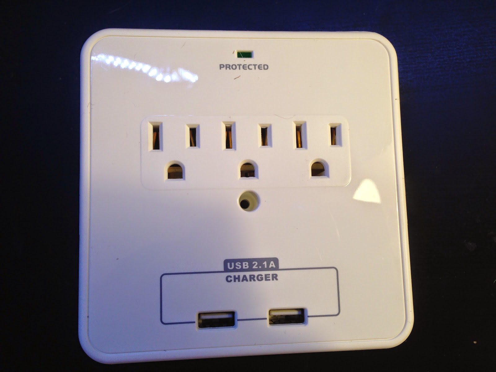
I planned on 3D printing a chassis to hold the plugs, parts, and electronics, but by luck I got an awesome gift for Christmas and ran across a blog post just in time for my own project. My sister gave me a 3-Outlet Wall Mount Surge Protector with USB Charging and Slide-Out Smartphone Holders for Christmas and I had planned on mounting it in the kitchen to charge phones. That is, until I saw this post, Wifi Enabled Outlet with VoCore. He uses a similar outlet for his project. I was reluctant to rip apart a new Christmas present, but it was such a perfect fit, that I couldn't help but do so.
The surge protector's shiny face
And its guts
Since I now have a suitable chassis, I needed to create the permanent circuit to finish the project. I used a small perfboard that I had and cut it into two halves to make it fit inside the surge protector. I mounted the two circuits on the sides where the smartphone holders used to reside. One side holds the Spark core on some female headers, the op-amp circuitry and opto-isolator connections, and a screw terminal for one of the lamp switches. The other side holds the transmitter, and the second screw terminal for the other lamp switch. Four wires are run between the circuits for power, ground, TX, and button input. All of the additional circuitry is powered from the Spark's USB connection. I decided to make it very easy to remove the Spark if I ever need to connect it to a computer for any reason (And good thing I did! A power surge caused the Spark's firmware to become corrupted, and I spent a good deal of time trying to get it usable again).
I used an AC plug from a cell phone charger to detect the light switch's AC input. This caused the only major screw-up in this project. When I thought the project was complete, I plugged it in to test it and when I toggled the light switch's AC line, the isolation that I installed wasn't strong enough and the AC voltage destroyed the internal 5V USB power supply. I attempted to replace this power supply with some others that I had on hand, but they did not have the same form factor and wouldn't fit without modifications. This is when I cut my losses and used an external Anker 20W 2-Port USB Wall Charger. This charger is perfect because it supplies enough juice to reliably power the Spark when communicating over Wi-Fi and charge an iPhone or iPad on the other port. This leaves me exactly enough AC receptacles and USB plugs to power what is usually plugged in, so I was content, but still upset that I had to go this route. On the bright side, there is a lot more room in the surge protector now for extra circuitry if I decide to add extra functionality later.
Mount the circuit to the side with a screw
Circuits on the sides with 4 wires running between
After the USB dilemma
Spark on one side
433Mhz transmitter on the other
Lastly, I plugged this circuitry into the wall and plugged the wireless relays into a power strip. I also ran the wires with the buttons under both night stands so they aren't visible, but still easily accessible.
The final circuitry plugged into the wall
The lamps plugged into the wireless relays
A button hidden under the nightstand
Just as I was finishing up the project, I had a nice surprise! Spark announced their channel on IFTTT. I initially had thoughts of creating a similar web app to the one I use for my electric imp outlet, now I don't have to. Without writing any new code, or changing my existing code, I was able to create a recipe that allows me to control the state of my lamps using Launch Center Pro. There is also the option of setting a time that the lights automatically turn on and off. Or even using geolocation to turn the lamps on when I get near home! I'm really excited to see what other uses I can come up with for this connection.
My custom actions to control the lights
There you have it. A relatively simple project that solves a inconvenience for me. Best case, this project will save me a couple minutes of frustration every day. But that's good enough for me. As a bonus, here's a photo album with some extra photos of the build. Also, my Spark code is hosted on Github.


No comments:
Post a Comment