Monday, August 27, 2012

Google Chrome Remote Webcam Viewer

     Chances are you don't have the equipment necessary to set up a security system just lying around, right? Well, you may be wrong. With only two computers - one with a webcam - and the Google Chrome browser installed on both, you have a rudimentary security system.

     First, we'll set up the computer that will be connected to the webcam. Chances are this will be a laptop - because it seems that most - if not all - laptops these days have a built-in webcam. You should also be able to use a desktop or laptop with a USB webcam too, which might be ideal for placement purposes. On this computer, install Google Chrome version 21 or above (version 21 includes support for a new API that allows the browser to access the webcam - don't worry, there's lot of warnings when you turn it on so you won't have someone spying on you without your knowledge). Once Chrome is installed, go to the Chrome Remote Desktop BETA's Chrome Web Store link and install it (Note: This app requires at least Windows Vista or newer to work - for "security" reasons). Once it is installed, launch it and follow the simple steps to get it configured.

     Now we will install Google Chrome on the viewer computer. The version does not specifically matter - as long as it can run the Remote Desktop app. Install the same Chrome Remote Desktop BETA app on this computer and configure it as well. When you check out the app on the viewer computer, it will list your other computers along the bottom. Click on the cam computer you want to connect to and you will be prompted to enter the pin you set up when you configured the app. Open the HTML5 Webcam Toy link on the cam computer and allow the site to connect to the webcam. You can now remotely view the webcam's video from another computer exclusively using Google Chrome - a program that doesn't require administrative rights to install. Have fun with it!

DISCLAIMER: Don't use this process to spy on things you shouldn't be looking at. I'm only posting this as a neat novelty use of technology. I will not be held responsible for any possible trouble you get yourself into using this technique.
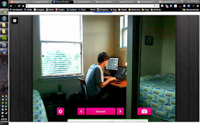
View on the viewer computer

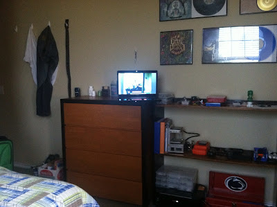
The cam computer is set up behind me

Friday, August 17, 2012

Filament Spool Stand

     When I first saw Cubic Print's Filament Spool, I knew it was something that I needed to make. You can only print with air-spooled filament for a couple prints before it gets tangled and you go crazy (I would know). It's a fantastic print, but it certainly needs to be attached to something to be used to it's full potential. I had originally planned on mounting it vertically like I've seen the majority of spool holders do, but then I decided I could slim down the design by making the spool sit horizontal, just like I used to have my filament sitting. My final design files ended up under Filament Spool Stand by Dillon1337 on Thingiverse. With 10 printed parts and less than $10 in parts, I had a very useful filament spool stand. Read on for the full scoop.

My usual 3D printing workspace

Thursday, August 16, 2012

My 3D Prints Summary #1

     Every once and a while I want to make a quick blog post highlighting some of the things that I've printed using my Printrbot LC 3D printer. These posts will be used to show off the prints that wouldn't be part of a larger project and are mostly just standalone pieces. This is the first of these posts. Check after the break for a more detailed breakdown.

Most of the good stuff I've printed so far

Wednesday, August 15, 2012

Printrbot Calibration Prints

     It's one thing to get a 3D printer set up to produce nice-looking prints, but it's another if those prints don't come out the size that you want them to. This quick post will help anyone get the axes on their 3D printer working just as they should. To make the most out of this post, you're going to need a pair of calipers.

Various calibration prints

Monday, August 13, 2012

Automatic Garden Waterer: Part 2

     This Automatic Garden Waterer project has kept me busy all summer long. Last time I posted about it, I had (mistakenly) thought it was finished, but issues with the solenoid valve caused me to take another path with it and create a new controller. I can confidently say that the new controller, not only functions a lot better, but looks much nicer while doing it. This is my first project using an Arduino, 16x2 character LCD, and 3D printing along with my other skills to create a cohesive product. Below is a video overview of the completed project, and below the break is all the work that occured to make it happen.


Monday, July 23, 2012

Printrbot Tip: Leveling the Printrbed

     Shortly after assembling and caibrating my Printrbot, I was able to print out my first object (Mr. Jaws by Mahoney in case you were wondering), but it took me a few tries to get the first layer to lay down right. I was able to get it working by increasing the bed temperature for the first layer to 130C from the default of 110C. I am unable to see what the actual temperature of my bed is, because the only thermocouple that I have was not working, but it should be close. Even with the higher temperature, I still had some troubles with parts laying down. Although I did try and level the bed the best I could, I rechecked it and it definitely needed some more work. After messing around with it for a while longer, I figured out the best way to get everything as level as possible.


Bed leveled with washers


     As Brook suggested, the bed needs to be leveled with washers on the four corners. After some time, I figured out that the best way to do this is to put the same size washer under each corner so you have the ability to move each corner up or down as needed. I used a pair of Digital Calipers to measure the thickness of the washers I had. The majority of them seemed to be 1.5mm so I used that as the base on each corner, but I also had washers with thicknesses of 1.3mm, 1.4mm, 1.6mm, 1.7mm, among others so I could swap the washers out to get small adjustments in the Z-direction in each corner. I once again checked the area of the Printrbed with a slice of paper in between the bed and the extruder tip, and although it was not perfect, the next object that I printed came out without a hitch. That object, by the way, was Pi Keychain / Backpack Charm by CodeCreations.


Freshly printed keychain

Although I only printed it because it was simple,
it should prevent me from losing this flash drive.

Thursday, July 5, 2012

Printrbot Build: Part 2

     I finished assembling my Printrbot LC last night. I still have to calibrate everything and make adjustments, but I now have a 3D printer that I am able to control over Pronterface. You can view the assembly from Part 1 here. Below is a video of the printer moving each of the stepper motors, and below the break are the photos from the build.


Wednesday, July 4, 2012

Printrbot Build: Part 1

     A long time ago (December 17, 2011 to be exact), I backed a Printrbot LC on Kickstarter. After months of waiting, I finally received my 3D printer yesterday and quickly started assembling it. I followed Brook's How-To Build videos on YouTube and got pretty far in a couple hours. I took (many, many) pictures along every step of the way so I thought I'd share them with you. Hopefully they can be beneficial to somebody, or at least help them decide if building a 3D printer is something they could do.

My workspace

Tuesday, June 26, 2012

Automatic Garden Waterer: Part 1

     A while ago I got my hands on a solenoid valve and wanted a project to use it in. If you followed my blog since the beginning, you would know that last summer my girlfriend and I started a garden at her house. She has a hose that is run to raised beds with a garden soaker hose to water the plants. Although it isn't difficult to turn a spigot to begin watering the plants, it is a problem remembering to turn the water off. From this idea, I finally knew what I was going to use that solenoid valve for. Read on for the details.

Front panel

Spoiler alert: I wrote this blog post before realizing that the solenoid valve was normally open, when I expected it to be normally closed. The electronics were made specifically for one function and I cannot use them with a normally open valve. I will make new (and better!) control circuitry and create a new post about it. This post goes through everything I worked on to get the original design to where it is now. Look forward to Part 2 for details on the final working product.

Tuesday, June 19, 2012

Father's Day Phones

     When my dad built the garage located on our property 30+ years ago, he ran a two conductor cable from the house so that he could install some phones in the garage. Needless to say, that never happened... until this past weekend. My parents recently found some corded phones at a yard sale and they rekindled my dad's interest in wiring the phones in the garage. Read on to see what I did.

It lives!

Wednesday, May 30, 2012

Some More Shelves

     As much as I enjoying designing and building electronics, it seems that I always end up making a project out of wood. I'm not exactly sure why I like it... It could be because it's so simple to fix mistakes or that it was my dad's hobby too, but I keep coming back. In this post I'll show you a storage shelf and a CD rack that I made.

Storage Shelf

CD Rack

Tuesday, May 29, 2012

Continuity Checker

     While working on my Homebrew Gameboy Cartridge PCB, I needed a way to check the connections on the board. Unfortunately, my cheap multimeter doesn't have a continuity checker, so I had to make one myself. It's a very easy circuit based on a 555 timer. I made it on a scrap piece of PCB and mounted it into the remains of a Wireless Door and Window Alarm that I used parts from on another project. It was the perfect fit because it could be battery powered and already has a buzzer built it.


How (Not) To Fix A Stereo Amplifier

     I've been using my parent's old stereo amplifier at school to play some tunes in the living room. It lasted almost two semesters but near the end of last semester, one of the channels was cutting out and eventually they both died. I know that large electriclytic capacitors are prone to going bad so I checked those first. Sure enough, they were swollen. I got my hands on a suitable replacement and hacked a way to switch the new ones in for the old, but unfortunately the replacements didn't fix the problem. Since this didn't bring it back to life, and with the stereo being so old, I'm going to put it into the junk pile for scavanging parts from it later on. I had hoped switching the capacitors would do the trick so I took pictures along the way to write a blog post about. Even though it didn't work, here's some photos of what I did.

Pioneer SA-940

Sunday, February 12, 2012

MSP430 Reaction Game

     I just finished my write-up on my MSP430 Reaction Game project. This project had a lot of firsts for me; first PCB design and manufacture, first time using github to host and version files, and first time using a microcontroller in a project. The object of the game is to stop the cycling LEDs at a specific LED to test your reaction skills. The TI MSP430G2231 microcontroller drives 8 LEDs via 3 pins using a 74HC595 shift register. The speed that the LEDs flash is determined from the potentiometer wiper via the analog to digital converter in the MSP430. There are also 2 pushbuttons to start/restart and stop the game. Everything is powered from a 9V battery that is dropped down to 3.3V via a LD1117V33 voltage regulator. There is also a programming header to program the microcontroller in-circuit with a TI Launchpad.

Check out the link below for a video walkthrough and all the juicy details. Enjoy! 

Monday, January 16, 2012

5V Regulated Breadboard Power Supply

     I recently got a PCB for this Breadboard module for 18-pin PIC16F microcontrollers from Raj and was looking through the tutorials on his website and thought it would be a great place to start learning about PICs. I have programmed PIC chips using PicBasic Pro, but I have never used C to program them. I knew having an easy to use power supply for prototyping would come in use, but I didn't have one. I know that Sparkfun and Adafruit each have their own solutions, but when I saw Raj's Regulated Power Supply for Your Breadboard, I knew I could easily make my own with parts I had in stock. Check after the break for how I did it.

Working product

Thursday, January 5, 2012

Homemade Variable Power Supply

     A while ago, I got two of these Graymark Model 803 variable power supplies. Unfortunately, they were sold as a kit and whoever assembled them before me did not do a very good job. To make matters worse, I could find no information online about this particular kit so I couldn't figure out how the circuit was supposed to be connected. It also had a mystery voltage regulator chip that I could never find any information about online. I decided that I would just go ahead and start over, using only the layout with new electronics for a new power supply.

Finished project

Tuesday, January 3, 2012

Making LadyAda's MiniPOV3

     A while ago I was struck with the idea of making a persistence of vision device. I have seen various contraptions all over the internet that would write out text or make images and I wanted to see what all the hoopla was about. I settled on a MiniPOV3 designed by LadyAda because it seemed very simple and I had nearly all the parts necessary to assemble it in my stockpile.

That's right. I'm a tinkerer.